Advertisement:
Read Later
In this article, I will give you information about DC motors, also known as electronic motors, and how you can control them using Arduino to create electronics projects with mobility and agility easily. Even though you are a novice in programming with Arduino or creating electronics projects with DC motors, it is simple to use them with a few lines of code, and some necessary components, depending on which method you use, will be explained later.
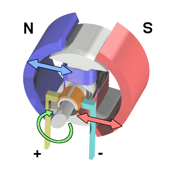
A direct current (DC) motor is a type of electric machine that converts electrical energy into mechanical energy with the help of the magnetic field generated in the device. In other words, DC motors take electrical power through direct current and transform this energy into mechanical rotation. But, how are they able to convert the electrical energy to the mechanical rotation?
The motor features a permanent horseshoe magnet (called the stator because it’s fixed in place) and a turning coil of wire called an armature (or rotor, because it rotates). The armature, carrying current provided by the battery, is an electromagnet because a current-carrying wire generates a magnetic field; invisible magnetic field lines are circulating all around the wire of the armature. The key to producing motion is positioning the electromagnet within the magnetic field of the permanent magnet (its field runs from its north to south poles). The armature experiences a force described by the left-hand rule. This interplay of magnetic fields and moving charged particles (the electrons in the current) generates the torque that makes the armature spin.
In today’s field of engineering and technology, you can find different types of direct current (DC) motors specialized for varying tasks and features for diverse electronics projects. And, there are two different designs for DC motors, depending on the commutator standard, under which all DC motors types are classified - brushed DC motors and brushless DC motor.
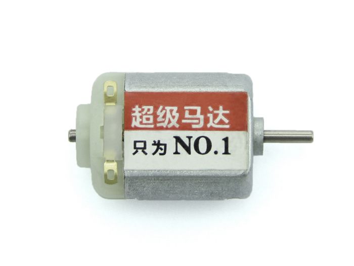
Brushed DC motors, which are also known as the original DC motors, generate torque directly from DC power supplied to the motor, using internal commutation, stationary magnets (permanent or electromagnets), and rotating electromagnets. They are known as the original DC motors because their design is dating back to Sprague’s initial design, who invented the first practical DC motor design in 1886(1).
In that design, DC running through the wire winding creates the magnetic field. Each time the armature rotates by 180°, the position of the north and south poles is reversed. If the magnetic field of the poles remained the same, the rotor would not turn. In other words, to create torque in one direction in a DC motor, the direction of the electric current must be reversed with every 180° turn of the armature. In a traditional brushed DC motor, this process is handled by the commutator that periodically reverses the current direction between the rotor and the external circuit. The commutator ensures the motor rotates in one direction and is composed of soft contacts named brushes. Through brushes, the commutator allows each armature coil to be energized in turn and connects the rotating coils with the external power supply.
As an example, you can inspect a brushed DC motor with large output force and high speed from the link below:
https://www.seeedstudio.com/130-DC-Motor-p-2023.html
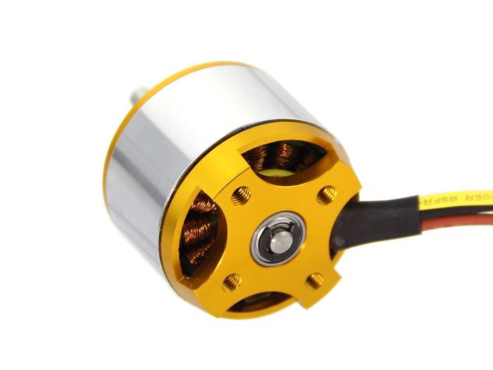
Due to the development of semiconductor electronics in the 1970s, engineers created a new and more efficient motor design – brushless DC motors - for particular tasks by eliminating the commutator. So, conversely, in the brushless DC motor design, an electronic sensor detects the angle of the rotor instead of a commutator, with controlled semiconductor switches either reversing the direction of the current or turning it off at the correct time in the rotation to create torque in one direction. We can say that this design is the enhanced version of the former design. But, how does the brushless DC motor design work without the commutator?
In DC motors with the brushless design, an electronic servo system replaces the mechanical commutator contacts. In that regard, an electronic sensor detects the angle of the rotor and controls semiconductor switches such as transistors, which switch current through the windings, either reversing the direction of the current or in some motors turning it off, at the correct time each 180° shaft rotation. So, the electromagnets create torque in one direction. As compared, the elimination of the sliding contact allows brushless DC motors to have less friction and longer life than brushed DC motors(2).
You can inspect this product below with the brushless DC motor design and high-quality bearings from here:
https://www.seeedstudio.com/Emax-XA2212-12V-DC-1400KV-Brushless-Motor-p-1900.html
Under brushed and brushless DC motor designs, the DC motor types include:
The permanent magnet DC motor (also known as a PMDC motor) consists of an armature winding but does not necessarily contain the field windings. The construction of these types of DC motors can be explained as that radially magnetized permanent magnets are mounted on the inner periphery of the stator core to produce the field flux.
As the name suggests, for a separately excited DC motor, the supply is given separately to the field and armature windings. The main distinguishing fact in these types of DC motor is that the armature current does not flow through the field windings, as the field winding is energized from a separate external source of DC current.
In a shunt wound DC motor (or more specifically shunt-wound self-excited DC motor), the field windings are exposed to the entire terminal voltage as they are connected in parallel to the armature winding.
In a series wound self-excited DC motor or simply series-wound DC motor, the entire armature current flows through the field winding as its connected in series to the armature winding.
The compound excitation characteristic in a DC motor occurs by combining the operational characteristic of both the shunt and series excited DC motor. So, the compound wound self-excited DC motor (or compound wound DC motor), essentially, contains the field winding connected both in series and in parallel to the armature winding.
If the shunt field winding is only parallel to the armature winding and not the series field winding, then it's known as short shunt DC motor or, more specifically, short shunt type compound-wound DC motor.
If the shunt field winding is parallel to both the armature winding and the series field winding, then it’s known as long shunt type compounded-wound DC motor or, more specifically, long shunt DC motor.
In a differentially compounded self-excited DC motor (or differential compound DC motor), the arrangement of shunt and series winding is such that the field flux produced by the shunt field winding diminishes the effect of flux by the main series field winding.
Although there are umpteen ways to control a DC motor with Arduino, in this article, I will focus on the two commonly used methods with simple steps for even beginners.
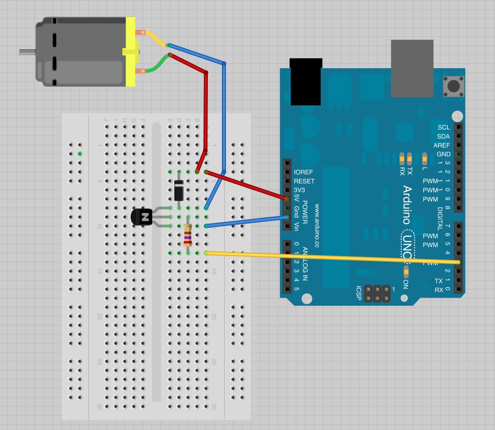
In the first method, we will use a transistor to control a DC motor with an Arduino Development Board by adjusting the average value of the voltage going to the electronic device (DC motor) by turning on and off the power at a fast rate via PWM (pulse width modulation).
Required Components:
Make the connections as depicted in the schematic below. And, do not forget that the flat side of the transistor should be on the right-hand side of the breadboard.
After completing connections, upload the code below to the Arduino to control the DC motor, which allows you to use the Serial Monitor to control the DC motor.
int motorPin = 3;
void setup()
{
  pinMode(motorPin, OUTPUT);
  Serial.begin(9600);
  while (! Serial);
  Serial.println("Speed 0 to 255");
}
void loop()
{
  if (Serial.available())
  {
    int speed = Serial.parseInt();
    if (speed >= 0 && speed <= 255)
    {
      analogWrite(motorPin, speed);
    }
  }
}

// Also, you can use a potentiometer to adjust the speed of a DC motor in this method.

int motorPin = 3;
int potentiometer = A0;
void setup()
{
  pinMode(motorPin, OUTPUT);

}
void loop()
{
  int speed = map(analogRead(potentiometer), 0, 1023, 0, 255);
  analogWrite(motorPin, speed);
}
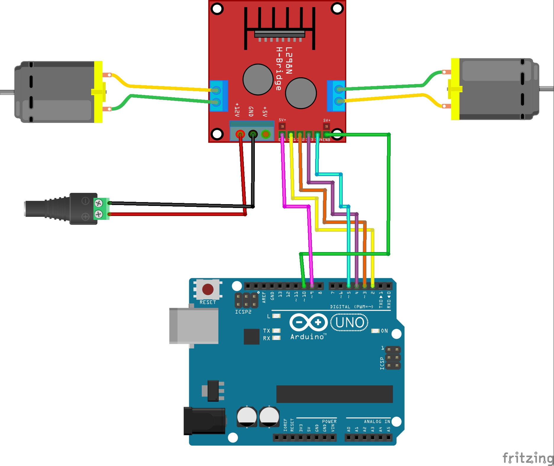
In the second method, we will use a dual H-Bridge motor driver allowing speed and direction control of two DC motors at the same time. This approach has more features than the former method without including redundant wirings and components. And, it is more convenient for electronics projects projecting hasten movements such as a robot car.
Required Components:
You can inspect an L298 Dual H-Bridge Motor Driver which uses ST L298N dual full-bridge driver from the link below:
https://www.seeedstudio.com/L298-Dual-H-Bridge-Motor-Driver-p-284.html
Make the connections as depicted in the figure below.
Then, upload the code below to test the features of the L298N Motor Driver. By using PWM to change the duty cycle, it increments the speed of both DC motors attached to the L298N Motor Driver and makes them go forward, backward, and stop. And, do not forget that you need to connect PWM pins to the enable pins (A and B) in order to control the speed of DC motors.
#define IN_1 D2
#define IN_2 D3
#define IN_3 D4
#define IN_4 D5
#define enA D9
#define enB D10

int speed = 0;

void setup()
{
  pinMode(IN_1, OUTPUT);
  pinMode(IN_2, OUTPUT);
  pinMode(IN_3, OUTPUT);
  pinMode(IN_4, OUTPUT);
  pinMode(enA, OUTPUT);
  pinMode(enB, OUTPUT);
}

void loop()
{
  // Speed:
  speed++;
  if(speed > 255) speed = 0;
  analogWrite(speed, enA);
  analogWrite(speed, enB);

  // Motor 1:
  // Forward
  digitalWrite(IN_1, HIGH);
  digitalWrite(IN_2, LOW);
  // Backward
  digitalWrite(IN_1, LOW);
  digitalWrite(IN_2, HIGH);
  // Stop
  digitalWrite(IN_1, LOW);
  digitalWrite(IN_2, LOW);

  // Motor 2:
  // Forward
  digitalWrite(IN_3, HIGH);
  digitalWrite(IN_4, LOW);
  // Backward
  digitalWrite(IN_3, LOW);
  digitalWrite(IN_4, HIGH);
  // Stop
  digitalWrite(IN_3, LOW);
  digitalWrite(IN_4, LOW);
}
Modifying this code, you can create Bluetooth or IoT enabled robot cars, wireless drones, or 3D printers. The limit is your imagination with DC motors.
(1) https://en.wikipedia.org/wiki/DC_motor
(2) https://en.wikipedia.org/wiki/Brushless_DC_electric_motor