I have had a dilapidated desk lamp for a long time, which waits in a box due to its outdated design with insipid features. Hence, I decided to improve my old lamp as my new desk lamp for my home office with new intriguing features. Despite the fact that it had no room for adding new parts in its base, I designed a PCB to put all components on the top of it. And, oddly enough, this design gave a steampunk-esque vibe to the lamp :)
To enhance my old lamp by superseding tasteless features, I decided to add a personalized lock removed by an RFID key merely to turn on the light. And, to set the lock again, I wanted to use a specialized color scheme. Thus, for enabling RFID to turn on the lamp, I used an Arduino Nano, an MFRC522 RFID Module, and a 2-Way Relay. But, I would still need to create a locking pattern entry system for my project, so I used three potentiometers (with knobs) to adjust the color pattern and an RGB to show it.
After completing my project, I designed the mentioned PCB with the unique triangular shape complementary to the lamp.
Huge thanks to JLCPCB for sponsoring this project.
Figure - 48.1
Step 1: Designing and Soldering the RFID Desk Lamp v2.0 PCB
I designed the RFID Desk Lamp v2.0 PCB by using KiCad. I attached the Gerber file of the PCB below, so if you want, you can order this PCB from JLCPCB to renew your older lamps as I did :)
Figure - 48.2
First of all, by using a soldering iron, I attached headers, resistors, the power jack, RGB, 5mm green LED, and potentiometers.
Component list on the PCB:
Nano (Headers for Arduino Nano)
RFID (Headers for MFRC522 RFID Module)
Relay (Headers for 2-Way Relay)
RGB1 (RGB)
LED (5mm Green LED)
J5 (Power Jack)
R1, R2, R3, R4 (220Ω Resistors)
RV1 (Red Pot.)
RV2 (Blue Pot.)
RV3 (Green Pot.)
Figure - 48.3
Figure - 48.4
Figure - 48.5
Even though there are no SMD components on the board, if you want, you can order a stencil to apply solder paste to the holes as I did, especially for soldering a headerless Arduino Nano.
Figure - 48.6
Step 2: Registering and Reading UIDs with the MFRC522 RFID Module
Download the required library for the MFRC522 RFID Module from here.
Not surprisingly, it is simple to register and read UIDs with the MFRC522 RFID Module: approximate the RFID card or key to the module and run the code for reading or registering.
To save a new UID to the EEPROM, uncomment the registerCardUID() function and run the code:
int registerCardUID() {
  // Detect the new card UID.
  if ( ! mfrc522.PICC_IsNewCardPresent()) {
    return 0;
  }
  if ( ! mfrc522.PICC_ReadCardSerial()) {
    return 0;
  }

  // Display the new UID.
  Serial.print("\n----------------------------------\nNew Card or Key Tag UID : ");
  for (int i = 0; i < mfrc522.uid.size; i++) {  //
    readCard[i] = mfrc522.uid.uidByte[i];
    Serial.print(readCard[i], HEX);
  }
  Serial.print("\n----------------------------------\n");

  // Save the new UID to EEPROM.
  for ( int i = 0; i < mfrc522.uid.size; i++ ){
   EEPROM.write(i, readCard[i] );
  }
  Serial.print("UID is saved successfully to the EEPROM.\n");

  // If the card registering process is successful, return 1 and end the reading process.
  mfrc522.PICC_HaltA();
  return 1;
}
To get the saved UID in the EEPROM, run this code:
int get_saved_UID(){
  // Get the saved UID in the EEPROM.
  for(int i=0;i<4;i++){
    savedUID += EEPROM.read(i) < 0x10 ? " 0" : " ";
    savedUID += String(EEPROM.read(i), HEX);
    }
  // Arrange the savedUID for comparison.
  savedUID.trim();
  savedUID.toUpperCase();
}
To compare the saved UID in the EEPROM and the currently read UID by the RFID module, execute this code:
int UID(){
  // Get the last UID from MFRC522.
  if ( ! mfrc522.PICC_IsNewCardPresent()){
    return;
  }
  if ( ! mfrc522.PICC_ReadCardSerial()){
    return;
  }
  for(int i=0;i<mfrc522.uid.size;i++){
    lastRead += mfrc522.uid.uidByte[i] < 0x10 ? " 0" : " ";
    lastRead += String(mfrc522.uid.uidByte[i], HEX);
  }

  // Arrange the lastRead for comparison.
  lastRead.trim();
  lastRead.toUpperCase();


  // Remove the LOCK if the UID is accurate.
  if(lastRead == savedUID){
    LOCK = false;
    while(LOCK == false){
      // Get potentiometer data from 0 to 255.
      readPotentiometer();
      // Adjust RGB led colors in regard to potentiometer values.
      adjustColor(red, green, blue);
      // Turn relay and controlLed on.
      digitalWrite(controlLed, HIGH);
      digitalWrite(IN_1, LOW);
      // Set the LOCK.
      if(red == 0 && green == 0 && blue == 0){
        LOCK = true;
        // Blank the lastRead.
        lastRead = "";
        }
      }
    }
}
For more detailed information about the code, please go to the following step.
Step 3: Programming the Arduino Nano
- Include the required libraries.
- Create the MFRC522 instance.
- Define the MFRC522 module key input.
- Define the readCard byte array storing the scanned ID read by RFID Module.
- Define the data holders.
- Define the LOCK boolean to either set or remove the LOCK.
- Define RGB pins, the controlLed pin, and potentiometer pins.
- Initialize MFRC522 Hardware.
- If you have not registered a UID to the EEPROM yet, upload the code after turning the emphasized lines uncommented.
- In the registerCardUID() function:
- Detect the new card UID.
- Save the new UID to the EEPROM.
- If the card registering process is successful, return 1 and end the reading process.
- In the get_saved_UID() function:
- Get the saved UID in the EEPROM.
- Arrange the savedUID for comparison.
- In the UID() function:
- Get the currently read UID by the MFRC522.
- Arrange the lastRead for comparing.
- Remove the LOCK if the UID is accurate.
- Get potentiometer data from 0 to 255.
- Adjust RGB colors in regard to potentiometer values.
- Turn on the relay and the controlLed.
- Set the LOCK if the RGB color scheme (0, 0, 0) is given.
After finishing and uploading the code to the Arduino, I attached the remaining components to the board through headers.
Figure - 48.11
Figure - 48.12
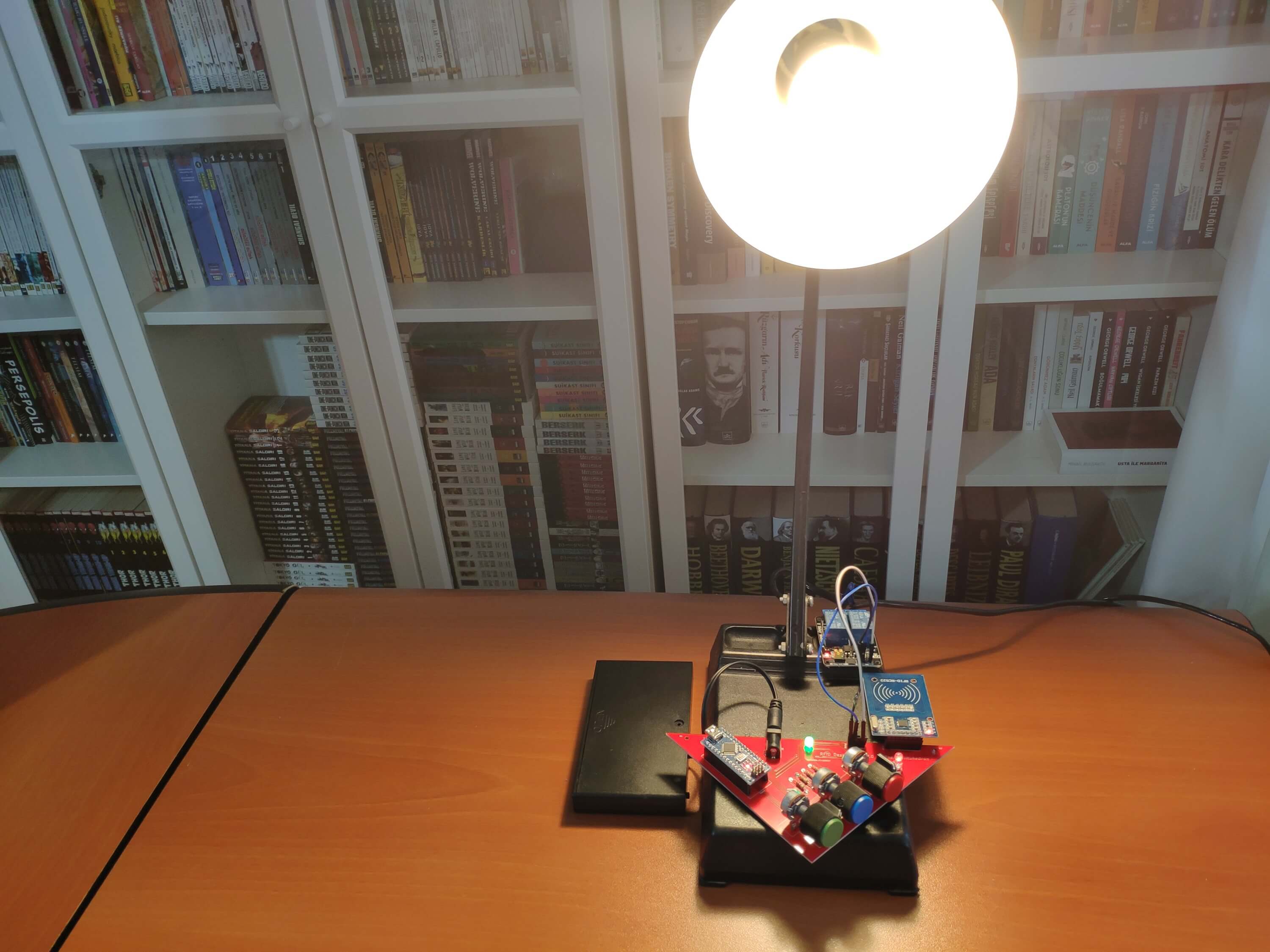
Then, I fastened the PCB to my lamp by using a hot glue gun and connected its cable to the 2-Way relay to control the light.
Figure - 48.13
Figure - 48.14
Features
1) Save a new RFID card or tag to the EEPROM to use it to remove the lock.
Figure - 48.15
2) To remove the lock, and be able to adjust the RGB color pattern, approximate the registered RFID card or tag to the MFRC522 RFID Module.
The controlLed (5mm Green LED) turns on when the lock is removed.
Figure - 48.16
3) For activating the lock, apply the selected RGB color scheme. In this version - the pattern is 0, 0, 0 - you have to reduce all potentiometer values to zero (black). But, if you want to use a different pattern, you can change it in the UID() function.
The controlLed (5mm Green LED) turns off when the lock is set.
Note: You cannot adjust the RGB color pattern - turns off - while locked.
/////////////////////////////////////////////
// RFID Desk Lamp //
// with RGB Color Scheme Lock //
// --------------------- //
// (Arduino Nano) //
// by Kutluhan Aktar //
// //
/////////////////////////////////////////////
// Enhance a dilapidated desk lamp w/ insipid features into an RFID enabled one w/ personalized RGB scheme lock via Arduino.
//
// You can register a new UID with the code below (registerUID) by turning it into uncommented.
//
// By using three potentiometers, you can adjust the RGB color scheme.
//
// In this version, for activating the LOCK, you have to reduce all potentiometer values to zero (black). But, if you want to use a different pattern, you can change it in the UID() function.
//
// UNLOCK :
// When the current UID read by the RFID module is accurate and thus the controlLed is HIGH.
//
// LOCK :
// Red Potentiometer Value = 0
// Green Potentiometer Value = 0
// Blue Potentiometer Value = 0
//
//
// Connections
// Arduino Nano :
//                            MFRC522
// D9  ----------------------- RST
// D10 ----------------------- SDA
// D11 ----------------------- MOSI
// D12 ----------------------- MISO
// D13 ----------------------- SCK
//                            5mm Green LED (controlLed)
// D2  -----------------------
//                            RGB
// D3  -----------------------
// D6  -----------------------
// D5  -----------------------
//                            2-Way Relay
// D7  ----------------------- IN_2
// D8  ----------------------- IN_1
//                            Potentiometer (Red)
// A0 -----------------------
//                            Potentiometer (Green)
// A1 -----------------------
//                            Potentiometer (Blue)
// A2 -----------------------
/*
Typical pin layout used:
-----------------------------------------------------------------------------------------
MFRC522 Arduino Arduino Arduino Arduino Arduino
Reader/PCD Uno/101 Mega Nano v3 Leonardo/Micro Pro Micro
Signal Pin Pin Pin Pin Pin Pin
-----------------------------------------------------------------------------------------
RST/Reset RST 9 5 D9 RESET/ICSP-5 RST
SPI SS SDA(SS) 10 53 D10 10 10
SPI MOSI MOSI 11 / ICSP-4 51 D11 ICSP-4 16
SPI MISO MISO 12 / ICSP-1 50 D12 ICSP-1 14
SPI SCK SCK 13 / ICSP-3 52 D13 ICSP-3 15
*/
#include <EEPROM.h> // We are going to read and write PICC's UIDs from/to EEPROM
#include <SPI.h> // RC522 Module uses SPI protocol
#include <MFRC522.h> // Library for Mifare RC522 Devices
// Create the MFRC522 instance.
#define SS_PIN 10
#define RST_PIN 9
MFRC522 mfrc522(SS_PIN, RST_PIN);
// Define the MFRC522 module key input.
MFRC522::MIFARE_Key key;
// Define the readCard byte array which stores the scanned ID read by RFID Module.
byte readCard[4];
// Define the data holders:
String savedUID;
String lastRead;
String successUID;
int red;
int green;
int blue;
// Define the LOCK boolean to either set or remove the LOCK.
boolean LOCK = true;
// Define RGB pins.
#define redPin 3
#define greenPin 6
#define bluePin 5
// Define the controlLed pin.
#define controlLed 2
// Define the relay pins (if needed, you can use both pins on the relay).
#define IN_1 8
#define IN_2 7
// Define potentiometer pins.
#define pot_r A0
#define pot_g A1
#define pot_b A2
void setup() {
Serial.begin(9600);
// Initialize MFRC522 Hardware
SPI.begin();
mfrc522.PCD_Init();
// If you have not registered a UID to the EEPROM yet, upload the code after turning these lines uncommented:
/*
// Save the new card or key tag UID to the EEPROM. But, do not forget it only has 1KB memory.
Serial.print("Approximate the new card or key tag to scan and register the new UID.\n");
do{
// Wait for the new card reading process.
successUID = registerCardUID();
}while(!successUID);
*/
// Get the saved UID in the EEPROM.
get_saved_UID();
Serial.print("UID is received from EEPROM :\n----------------------------------\n");
Serial.print(savedUID);
pinMode(redPin, OUTPUT);
pinMode(greenPin, OUTPUT);
pinMode(bluePin, OUTPUT);
pinMode(controlLed, OUTPUT);
pinMode(IN_1, OUTPUT);
pinMode(IN_2, OUTPUT);
}
void loop(){
// Turn relay and controlLed off.
digitalWrite(IN_1, HIGH);
digitalWrite(IN_2, HIGH);
digitalWrite(controlLed, LOW);
// Remove the LOCK if the current UID read by the RFID module is accurate. Or, set it if the RGB Color Scheme Lock is given.
UID();
}
int UID(){
// Get the last UID from MFRC522.
if ( ! mfrc522.PICC_IsNewCardPresent()){
return;
}
if ( ! mfrc522.PICC_ReadCardSerial()){
return;
}
for(int i=0;i<mfrc522.uid.size;i++){
lastRead += mfrc522.uid.uidByte[i] < 0x10 ? " 0" : " ";
lastRead += String(mfrc522.uid.uidByte[i], HEX);
}
// Arrange the lastRead for comparison.
lastRead.trim();
lastRead.toUpperCase();
// Remove the LOCK if the UID is accurate.
if(lastRead == savedUID){
LOCK = false;
while(LOCK == false){
// Get potentiometer data from 0 to 255.
readPotentiometer();
// Adjust RGB led colors in regard to potentiometer values.
adjustColor(red, green, blue);
// Turn relay and controlLed on.
digitalWrite(controlLed, HIGH);
digitalWrite(IN_1, LOW);
// Set the LOCK.
if(red == 0 && green == 0 && blue == 0){
LOCK = true;
// Blank the lastRead.
lastRead = "";
}
}
}
}
int readPotentiometer(){
red = map(analogRead(pot_r), 0, 1023, 0, 255);
green = map(analogRead(pot_g), 0, 1023, 0, 255);
blue = map(analogRead(pot_b), 0, 1023, 0, 255);
}
void adjustColor(int r, int g, int b){
r = 255 - r;
g = 255 - g;
b = 255 - b;
analogWrite(redPin, r);
analogWrite(greenPin, g);
analogWrite(bluePin, b);
}
int registerCardUID() {
// Detect the new card UID.
if ( ! mfrc522.PICC_IsNewCardPresent()) {
return 0;
}
if ( ! mfrc522.PICC_ReadCardSerial()) {
return 0;
}
// Display the new UID.
Serial.print("\n----------------------------------\nNew Card or Key Tag UID : ");
for (int i = 0; i < mfrc522.uid.size; i++) { //
readCard[i] = mfrc522.uid.uidByte[i];
Serial.print(readCard[i], HEX);
}
Serial.print("\n----------------------------------\n");
// Save the new UID to EEPROM.
for ( int i = 0; i < mfrc522.uid.size; i++ ){
EEPROM.write(i, readCard[i] );
}
Serial.print("UID is saved successfully to the EEPROM.\n");
// If the card registering process is successful, return 1 and end the reading process.
mfrc522.PICC_HaltA();
return 1;
}
int get_saved_UID(){
// Get the saved UID in the EEPROM.
for(int i=0;i<4;i++){
savedUID += EEPROM.read(i) < 0x10 ? " 0" : " ";
savedUID += String(EEPROM.read(i), HEX);
}
// Arrange the savedUID for comparison.
savedUID.trim();
savedUID.toUpperCase();
}